FAQ and technical information/tips.
Below you'll find answers and tutorials to technical questions about our products.
Click on any question to reveal the answer.
What are the key requirements of a power supply for 5G?
The 7 fundamental technical features to consider before choosing a 5G power supply
Power supplies for 5G and telecommunications are not generic power supplies that simply need to provide a certain current; they must meet very specific requirements.
Here are the main features they must have:
Universal standard Using products that comply with a universal standard (such as, for example, DOSA – Distributed-power Open Standards Alliance) is always the best choice, as it ensures a series of intrinsic guarantees such as compatibility with other devices, package dimensions (1/4, 1/8, 1/16 brick) and the definition of other universal requirements. Standard package dimensions also allow designers to quickly replace products within the same package, avoiding hours of work and additional costs related to PCB redesign and recertification, which is also very useful for upgrading from 4G to 5G.
Wide operating temperature range In addition to ambient temperature, which generally ranges from -40°C to +70°C, power supplies and some components also heat up, bringing telecommunications equipment to very high temperatures. Naturally, only a power supply with a wider temperature range can meet operating temperature requirements of up to 100°C.
Higher efficiency
5G data flow is irregular and usage time is variable; for this reason, the efficiency and performance of power supplies used in the telecommunications field must not vary depending on the load, but must deliver maximum performance both at full load and “no load”.
Outstanding EMC performance
All electronic equipment strives for good EMC performance, so it is very important to choose a power supply with outstanding EMC performance.
Low standby power consumption to save energy
Standby power consumption is a kind of energy waste, and reducing it should be taken into account when designing the system.
High reliability In 5G telecommunications, reliability is crucial to guarantee high signal speed.
Cost-effective with fast, stable deliveries The development of 5G telecommunications requires large quantities of basic equipment, while also requiring low-cost power supplies with fast delivery and stable supply.
What are the charging MODES and the TYPES of cables/connectors for electric vehicles?
There are various charging modes and cables/connectors for charging electric cars.
We need to start with an essential premise: in this field, terminology is very important, since even what we think are synonyms for a device actually have different meanings. Let’s give an immediate example: MODES are the charging methods, while TYPES are the categories of cables/connectors used for charging. We will see other differences later on.
The first thing to consider concerns two closely interconnected concepts:
Charging contexts
Charging modes
Electric vehicle charging: home and public settings
Electric vehicle charging can take place in two settings:
Private: via the home electrical grid or a domestic wallbox
Public: via fixed structures, charging stations, wallboxes, EVSEs, or simply charging stations on public roads, streets, or on private land open to public use such as car parks, supermarkets, shopping centres, etc.
In the home setting, charging takes place in alternating current (AC), while in the public setting it can take place in alternating current (AC) or direct current (DC).
Based on the power delivered, public charging stations can allow: slowcharging, acceleratedcharging (quick), fastcharging or ultra-fast charging. Charging times depend not only on the power delivered by the charging station, but also on the power accepted by the onboard charger of the vehicle. If these two power values differ, the lower value prevails.
Charging duration ranges from 10-15 minutes (ultra fast) up to 6-9 hours.
Electric vehicle charging modes
There are currently 4 charging modes for electric cars, defined by the International Electrotechnical Commission (IEC 61851-1 standard): Mode 1, Mode 2, Mode 3 and Mode 4.
Here too, it’s worth making a brief premise. All batteries operate in direct current (DC), but as we will see, the first three charging Modes are in alternating current (AC), so how is it possible to charge the battery in these cases? The answer is simple: electric vehicles have a charger (or onboard charger) that also contains an AC/DC current converter.
Mode 1: the car battery is connected directly to the AC power grid through standard plugs and sockets (domestic or industrial), just like any household appliance. Charging can occur up to 16 A, either single-phase or three-phase. This mode is used for home charging of electric bikes, scooters or light electric vehicles with limited-capacity batteries, and in Italy it is not allowed for public charging for safety reasons, since it is the only charging process without a Control Box (normally in PWM – Pulse Width Modulation mode), which is essential to guarantee safety during the charging process.
Mode 2: AC charging that involves the use of a Control Box-PWM located between the electrical grid and the vehicle being charged, normally on the connection cable. The Control Box-PWM only manages safety on the vehicle side (from the box on the cable to the car). Charging can occur up to 32 A (with domestic or industrial sockets), single-phase or three-phase. In Italy, this mode too is allowed only in the home setting and not in public areas.
Mode 3: requires the use of equipment and fixed structures permanently connected to the electrical grid (for example, public charging stations). The standard requires that the Control Box-PWM be built into the charging station and perform the following functions: verifying connector insertion, verifying continuity of the protective conductor, and active control (in practice, the Control Box-PWM manages safety both on the vehicle side and on the charging station side). In Italy, this is the only mode allowed for AC charging in public settings.
Mode 4: is characteristic of Fast and Ultra Fast charging stations, where the direct current delivered directly to the electric vehicle’s battery does not require the additional work of the AC/DC converter onboard the car, since this converter is external and is contained in the charger included in the charging station (for clarity, this is the only charging mode in which the charger is not included in the vehicle, i.e. it is external to it and is contained in the charging station). In addition, the charging station also contains a pilot control conductor that extends to the equipment permanently connected to the grid. Unless specific national regulations apply, charging can reach a maximum of 350 kW (normally 22 kW) with CCS2 connectors (also known as COMBO2 – the European standard, therefore also used in Italy) or CHAdeMO (Japanese standard).
Other terminology and key elements required for charging
As mentioned at the beginning, terminology is essential to avoid confusion in a constantly evolving sector.
The terms “plug” and “connector”, as already mentioned at the start of this brief article, could easily be considered synonyms, but in this field they actually have completely different meanings.
Let’s look in detail at these terms and their meaning:
The flexible cable (cable) is used to establish the electrical connection between the electric vehicle and the charging system, and is fitted with a plug and/or a movable connector at its ends. It is also simply called the charging cable or cord-set.
The movable connector (referred to simply as connector in this text) is the coupling mechanism, attached to a flexible cable, that connects to the electric vehicle (in English it is called a connector, and is sometimes also referred to as a movable socket, which shows just how misleading this terminology can be…).
The fixed inlet on the vehicle (called an inlet or fixed connector in English) is the vehicle’s coupling mechanism, built into or attached to the electric vehicle.
The fixed socket outlet is installed in the fixed charging system to connect a flexible cable fitted with a movable plug to the electrical system.
Finally, we have the movable plug (plug), which is attached to the flexible cable and connects to the charging system via a fixed socket.
Connecting the electric vehicle to the charging station
To connect the electric vehicle to the power grid, there are currently three standardised types of connection:
Case A: The electric vehicle is connected to the charging point using a power cable and a plug permanently attached to the vehicle itself (normally Mode 1)
Case B: The electric vehicle is connected to the charging point using a removable power cable fitted with a movable connector (vehicle side) and a movable plug (charging station side) for connection to the AC power outlet (normally Mode 3; in Mode 2 a Control Box-PWM is required in the middle of the charging cable).
Case C: The electric vehicle is connected to the charging point using a power cable and a movable connector (vehicle side) permanently attached to the charging system (normally Mode 4).
Types of AC and DC charging cables/connectors
Now it’s time to talk about the different types of charging cables/connectorsfor electric cars.
It’s worth remembering that we refer to a socket/plug system on the charging station side, and to connectors when referring to the vehicle side.
The most commonly used connector types for AC vehicle charging are as follows:
Type 1: can deliver between 3 and 7.4 kW and only supports single-phase power up to 32 A 230V. It includes additional protection to lock the connector during charging, preventing disconnection. It is approved as the Japanese standard. Found only on the vehicle side.
Type 2: allows charging between 3 and 43 kW, up to 22 kW with a detachable cable (home setting) and up to 43 kW with a fixed cable (public charging stations). It can support single-phase and three-phase power up to 32 A 230/400V. It is approved as the European standard. Found on both the vehicle side and the charging station side.
For completeness, there are two other connector Types (on the charging station side): Type 3A (used only for light vehicles such as scooters and quadricycles) and Type 3C, now obsolete. Finally, in Mode 1 the permanent plug is a standard household plug of the Schuko type (it can be found in Mode 1 but also in the Mode 2 charging cable with Control Box-PWM).
For DC vehicle charging (Mode 4) there are two connector types:
CHAdeMO: the most widely used standard in the world for fast DC charging, allowing charging up to 100 kW. Vehicles equipped with this standard have two connectors: a CHAdeMO connector for Fast DC charging and a connector for AC charging (usually Type 1).
CCS (Combined Charging System): this is a “combined” connector. In Europe, it is based on the Type 2 connector, to which two pins are added (hence it is also called CCS Combo2 or CCS2). It is specifically designed for DC charging, but can charge in both AC and DC up to 350 kW.
Understanding insulation classes for Power Supplies
Protecting the user from harmful energy levels is traditionally achieved by sufficiently insulating live components. How this is achieved, and to what level, determines which insulation class the unit will have. Below we detail the types of insulation and the three different equipment classes.
There are five insulation categories used by the different equipment classes: functional, basic, supplementary, double and reinforced:
Functional insulation: the basic level required for the power supply to operate. This does not prevent electric shock if touched.
Basic insulation: provides the user with a single, simple protection against electric shock.
Supplementary insulation: like basic insulation, it must withstand 1.5 KV AC (2.1 KV DC).
Double insulation: the combined use of basic and supplementary insulation to provide redundancy. If the basic insulation fails, the supplementary protection still protects the user.
Reinforced insulation: a single layer that works in the same way as double insulation
How is RADAR technology integrated with security systems? The great challenge!
The further development of radar sensors is opening up many possibilities for the security sector, but manufacturers of security equipment have difficulty implementing this technology in their products. They often lack the skills and development resources needed to deploy radar technology. Integrating this technology involves some obstacles that can hardly be overcome without the necessary know-how of radar technology.
Why Radar technology is complicated
Only a few companies worldwide specialize in this technology: they employ experts who have the necessary skills to handle radar technology. Their experience and know-how are based on years of learning. There are not many experts in this field. Manufacturers of security equipment rarely have such radar specialists within their own company. Even large companies depend on the assistance of experts.
Complex radar applications are gradually gaining acceptance and boast greater reliability, precision and functions. Furthermore, they excite security companies. However, implementing the radar component requires manufacturers of security equipment to invest time and labor. Radar integration is a real challenge.
What makes radar technology integration so difficult?
Beyond minor difficulties, such as hardware compatibility and correct product selection, signal processing is by far the biggest problem faced during integration. This starts with the right choice of processing method, which depends on the radar’s characteristics. Without in-depth knowledge, it is impossible to correctly analyze detections.
The following aspects require relevant expertise in Radar technology:
Prevention of interference signals and false detections
Like any measurement technology, radar does not always provide clean results. False detections must be recognized and corrected. Depending on the radar’s operating principle, bandwidth, distance, environmental factors and the object, the raw data has numerous specific effects. While useful signals such as the Doppler effect help detect an object, interference signals lead to redundant or erroneous detections. This must be taken into account in digital signal processing in order to ensure uncontaminated data. Using algorithms, the system reliably distinguishes between useful signals and interference signals.
Filtering of irrelevant detections
In order to implement more complex radar functions, extensive algorithms need to be developed. This involves a specific filter for the radar data application. In the security field, it is not enough to simply eliminate interference signals. The goal is to focus on particular events. The system must resolve detections triggered by animals, bushes, rain or wind. However, this goes well beyond basic algorithms.
Object classification
In addition to filters, the identification and observation of objects is an important aspect of digital signal processing. This requires classification and tracking through algorithms. Machine learning processes are required for this purpose. The technology is increasingly developing in the direction of artificial intelligence in order to detect patterns. Together with the representation of object data, this involves high labor costs in terms of software development.
Application testing and configuration
For application-specific signal analysis, a good deal of time must be devoted to application testing. Subsequent adjustments are based on the results obtained from this important aid to optimize signal processing and tracking. These tests under real conditions are extremely costly in terms of both cost and labor.
Real-time processing of data volumes
With complex radar systems equipped with numerous channels, high data volumes result. In the field of security technology, it is important that these are processed in real time. Delayed or interrupted transmission increases the security risk. To overcome this challenge, a suitable technical solution must be found and implemented without being subject to losses. Data processing must also be intensively addressed.
Implementing all aspects of radar technology integration involves extensive and lengthy development work. Most radar technology companies develop only front-ends or simple radar systems that work only with basic algorithms that digitize analog signals and filter out false detections. They normally do not cover more demanding functions such as object tracking, pattern recognition or classification. Until now, in-depth signal processing has often been a major obstacle for manufacturers of the finished security application. Some security equipment manufacturers therefore used to give up on complex radar applications. But with advances in technology, a new approach is now available to solve the problem.
Simpler integration with advanced radar solutions
In recent years, radar experts have made use of the latest technical discoveries available in the field of software development. The importance of signal processing has increased significantly: it allows increasingly complex tasks to be performed via radar economically. As a result, the trend is toward radar products that dare to take a crucial step toward the final product: from a radar component to a radar system.
These systems are equipped with advanced signal processing. They provide clean data, filtering out false detections or interfering signals. “Ghost tracks” are already taken into account during development. The systems also boast useful filter functions. This allows the user to focus on important events and hide anything that is not relevant.
Advanced systems have useful functions and thus improve ease of use for end users. They are already optimized and thoroughly tested to best meet the needs of the application. Measurement results are reliably retrievable and increasingly accurate. In order to develop such products, radar technology companies are increasingly expanding their range of activities. For example, they are working on application testing and algorithm development.
This preliminary work greatly simplifies radar integration. Security equipment manufacturers can use the system for their products without in-depth radar knowledge or integration work. This speeds up the crucial time-to-market phase and facilitates access to the technology.
InnoSenT’s Smart Tracker
The iSYS-5021 radar system is precisely such an innovation for the security industry. The available tracker license includes complete signal processing and the useful Smart Tracker functionalities.
System integrators used to display numerous radar detections, then correctly attribute them to an object and separate them. This task is now entrusted to the tracking function. The radar system groups individual radar detections into objects and tracks them over time. The movement line of people is displayed using tracks.
Important filter functions and object classifications are also available: the system distinguishes between people and vehicles and reliably filters out interfering factors such as rain or wind. Using a user interface, the user can set various configurations very simply and individually. For example, they define alarm and ignore zones to focus monitoring on certain areas. Radar experts have already successfully carried out the numerous application tests needed to calibrate the system and have optimally adapted the system for perimeter use and monitoring of large-scale outdoor facilities.
How to choose an external power supply? 6 key aspects for selecting an industrial external power supply
What are the characteristics to consider when selecting an external power supply? As Consystem, we highlight six essential elements not to be overlooked when choosing an industrial external power supply. Let’s look at them together
1. What are the system’s power requirements?
The first consideration when selecting a power supply is knowing the system’s power requirements. Understanding the power, voltage and current required by the system load is essential for the operation and safety of the final system. This includes asking questions such as: “Does my system run at constant power? Will I have a peak current?”
2. Package – “Desktop” power supply or wall-plug type?
External power supplies are generally offered in two package types: desktop or wall-plug (with a fixed plug or interchangeable plugs). For many applications, both solutions work well. However, there are some reasons why one may be preferable to the other.
For example:
Power range: “desktop” adapters are generally suited to higher-power applications, while “wall-plug” power supplies are ideal for lower-power applications. Desktop adapters are typically larger, which is why they can also deliver higher power.
Global market: If you intend to offer your product or project on the global/international market, multi-plug “wall-plug” solutions and “desktop” adapters are an excellent choice. The interchangeability of plugs (multi-plug “wall-plug” power supply) and of the input cable connector (“desktop” power supply) allows the same product to be used simply by changing the plug or cable connector to meet the socket standards of the target end market.
Grounding: “desktop” power supplies offer the option of a three-wire AC input (with ground) or two-wire (without ground). “Wall-plug” power supplies are only available with a two-pole AC input (without protective ground).
Size and portability: If the power supply will be located in a visible part of the final system or used in portable equipment, the aesthetics, size and weight of the power supply must be taken into account. High power density power supplies can help in these cases.
3. DC connector and plug options
Once the main characteristics have been defined, it is necessary to think about how the power supply will be connected in the final system: this leads to the selection of the output connector. There are various types of DC connectors, such as the DC plug connector (“barrel” type) or “P5”, but also micro USB, DIN, mini DIN, etc. Several options are available, including stripped and tinned cables, or a right-angle connector, depending on the configuration required by the system.
Another thing to consider is the output cable, to ensure it meets design requirements. Is it long enough to reach your product? Does it have the desired look and flexibility? It is important to understand that the choice and/or subsequent modification of the DC cable can affect both efficiency and safety standards.
4. Efficiency regulations, safety standards and Agency Marks
The distribution market for the final product is a critical point due to the different regulations and certifications required. Many countries have efficiency standards that regulate the amount of energy that can be “wasted” by external power supplies, such as Level VI for the US market.
In addition to efficiency standards, it is essential to make sure the adapter also has the safety certifications appropriate to the final application and market. For example, medical products require 60601-1 certification, and products for ICT/AV applications require 62368-1 certification.
Finally, some countries have their own Agency Mark, valid only for that country. Additional testing or customization of the design to certain specifications may be required to meet these requirements: CONSYSTEM has the experience and know-how to work with you and help you in these situations.
5. EMI and EMC
Many electronic products must meet EMI and EMC regulatory requirement levels (electromagnetic interference and electromagnetic compatibility). These requirements ensure that your product does not interfere with the proper operation of other products, and likewise that the proper operation of your product is not affected by other products. CONSYSTEM offers power supplies certified according to EMC and EMI regulations and, should it be necessary after testing the entire system, also has a complete range of certified and tested EMI filters.
6. System integration
Another important consideration and question to ask is “How will the chosen solution look within the overall system?”. If your final product has an appealing design and every detail has been carefully considered, why overlook the adapter? The possibility of customizing the power supply’s appearance should always be evaluated, for example with a specific color or by adding your own logo.
How to choose the right Panel PC?
The fundamental technical characteristics to consider in order to identify the Panel PC suited to your needs
To find the Panel PC compatible with your needs, you can follow a few criteria (some of which are listed below):
Panel PC Displays
Software applications are often still optimized for the 4:3 format with a screen resolution of 1024 x 786 pixels. For this reason, panel PCs with displays in this format are currently the best-selling ones. However, other formats are now also available, for example 16:9, which is the standard format for current desktop monitors.
Panel PCs available on the market can have screen diagonals ranging from 3″ to more than 30″.
For outdoor use, where daylight can significantly reduce screen readability, there is the “high brightness” option.
DIN protection class
For the use of electrical equipment in environments where there is a risk of foreign objects and moisture penetrating, the DIN EN 60529 standard (“Degrees of protection provided by enclosures”) specifies the so-called IP protection classes, consisting of the abbreviation IP (“ingress protection”) followed by two code numbers. The first indicates protection against foreign objects of various sizes, and the second against the ingress of water in various forms.
The IP65 protection class (very common), for example, guarantees dust-tightness of a device with the code number 6 and “protection against water jets from any angle” with the code number 5. It should be noted that some manufacturers only refer to the water protection class on the front. Maximum protection against water is provided by classes 8 (“protection against permanent immersion”) and 9 (“protection against water during cleaning with high-pressure/steam jets”), i.e. classes IP68 and IP69.
Panel PCs: resistive and capacitive touchscreen monitors
The first touch-sensitive screen was developed in the early 1970s at the CERN nuclear research center near Geneva. Since then, several variants have been built, differing in how the electronics locate the point touched. As mentioned above, touchscreens can be divided according to their respective functional principles into “resistive” and “capacitive”, each with different characteristics and advantages.
Advantages of resistive touchscreens:
Less expensive to manufacture;
More precise localization of the touched point, hence a lower likelihood of accidental misuse;
It also follows that the software used can offer smaller, and therefore more, selection buttons on the user interface;
The screen also responds to touch with non-conductive objects, such as plastic pens;
It can be used with gloves;
Less sensitive to heat and humidity.
Advantages of capacitive touchscreens:
Mechanically very robust; it still works even after the display has cracked (a phenomenon well known with smartphones);
Higher sensitivity, so less pressure is needed;
Ensures a sharper image thanks to higher contrast and brightness;
“Multi-Touch Sensing”: the ability to touch multiple points simultaneously (a prerequisite, for example, for zooming an image with 2 fingers).
CPU performance
Another selection criterion is CPU performance. In general, the more powerful and fast the CPU, the higher the price. Simple office programs and internet applications do not require the latest and most expensive CPU. With processing-intensive software, on the other hand, high CPU performance reduces annoying waiting times.
Cooling
Many Panel PCs do without cooling fans, replacing them with a heat sink that dissipates the CPU’s waste heat into the environment. The advantages of fanless cooling: mechanics less susceptible to wear inside the PC, minimal dust ingress, and: you can no longer hear anything from the PC.
Interfaces
Panel PCs are equipped with a wide range of interfaces, in addition to standard interfaces such as Ethernet and USB. When purchasing these products, it is important to consider which and how many interfaces are needed for your requirements.
Power supply
Panel PCs can have different power supply requirements. Some require a well-regulated power supply, for example 12 V or 24 V. Panel PCs that tolerate a wide input voltage range of 9 – 36 V are of interest for mobile use.
CONSYSTEM is a distributor of industry leaders such as Chipsee. It offers dedicated support from a technical specialist and the possibility of custom solutions.
When it comes to LiDAR, very few people know exactly what it is, how it works, and why it is becoming an increasingly important technology for the development of new self-driving vehicles and for ADAS (Advanced Driver Assistance Systems). Let’s find out more.
LiDAR technology: Light Detection And Ranging
The acronym LiDAR (Light Detection And Ranging) identifies the technology that measures the distance to an object by illuminating it with a laser light, while at the same time being able to return high-resolution three-dimensional information about the surrounding environment. A LiDAR typically uses several components: lasers, photodetectors and read-out integrated circuits (ROIC) with time-of-flight (TOF) capability to measure distance by illuminating a target and analyzing the reflected light. Basically, LiDAR is a technique similar to radar based on the echo principle. The same principle used by radar, which uses (pulsed) light as the “signal” instead of a radio signal.
Operation and use of a LiDAR system
The operation of LiDAR technology is based on an “immediate” principle: knowing that the speed of light propagation is fixed (C 300,000 km/s), it is easy to calculate the time it takes for a light beam to travel from a source to a (reflective) target and back to the light detector (placed next to the emitting light source, see image below).
This measurement principle is usually referred to as “Time of Flight” (ToF). The time of flight can be obtained by sending a pulsed signal via a laser, but also by measuring the phase and frequency of the reflected light signal relative to a reference signal.
Figure 1: illustrative example of the LiDAR operating principle
As shown in the illustration (Fig. 1), once the time taken by the light beam to make the “journey” (reach the target and return) has been timed, we can calculate the distance by multiplying the ‘time of flight’ by the speed of light and dividing by 2 (because the beam travels there and back), as shown in the formula.
Assuming the time taken is 60 nanoseconds, we get a distance of 9 m.
Applying this principle on a three-dimensional level, a ‘cloud’ of points can be obtained representing the distance of objects from the LiDAR sensor. The image represented by the point cloud can then be digitally processed to identify fixed or moving objects, or more simply to faithfully reconstruct the surfaces of the surrounding environment.
Figure 2: Point cloud measured by a LiDAR sensor reproducing the surrounding environment in 3D (Source: Elettronica Plus)
The two methods for building LiDAR systems
LiDAR systems are made up of fairly sophisticated components and, depending on their type, contain: laser sources and laser diodes, optical elements (lenses, mirrors and diffusers), elements for steering the emitted beam in space, photodetectors and signal processing units.
LiDAR systems are generally built according to two main methods: mechanical scanning (scanner) and fixed image (flash):
Mechanical scanning: in the mechanical scanning type, a LiDAR sensor physically rotates the laser and the receiver through 360° to obtain a very wide view. Mechanical scanning can be achieved by physically rotating or moving the emitter and light detector along the Cartesian axes, or by using controllable micromirrors made with MEMS (Micro Electro-Mechanical Systems) technology, as shown in Figure 3.
The field of view of a scanning LiDAR sensor is determined by the degrees of freedom and any movement constraints of the mechanical or MEMS scanning system.
Figure 3: Graphic representation of LiDAR mechanical scanning
The Flash LiDAR method: this involves no moving parts or components and is conceptually more similar to a snapshot. The field of view of a Flash LiDAR sensor is essentially determined by the characteristics of the optics that emit and receive the light beam (see Figure 4).
Figure 4: Graphic representation of Flash LiDAR technology
The wavelength of the emitted laser beam and the power at which it is emitted, together with the sensitivity of the light detector, are some of the factors that determine the visual range of the LiDAR and its ability to “identify” details. LiDAR systems can use various distance measurement methods; besides the time of flight of a pulse, they can measure the phase shift of the signal emitted by a continuous-wave (CW) laser or exploit frequency modulation (FMCW). These are measurement and signal processing techniques drawn from the long experience accumulated in the radar field, now adapted to the wavelengths of light signals.
Four types of LiDAR detectors
The light emitted by a LiDAR’s laser source propagates in various directions and, after being reflected by an object, must be received by the detector. During the detection process, the photons of the reflected light must be correctly identified, meaning that only those originating from the sensor’s original emission source are of interest. It is therefore necessary to prevent interference caused by any reflections generated by other active LiDAR systems in the same environment (spoofing), as well as those due to natural reflections of ambient light or other artificial light sources (clutter). In general, four main semiconductor technologies have become widespread for building LiDAR sensor detectors:
PIN photodiodes,
avalanche photodiodes (APD),
single-photon avalanche diodes (SPAD), and
silicon photomultipliers (SiPM).
Depending on the application, LiDAR detectors are built using either a single sensitive element or an array of detectors working in a coordinated manner, similar to the optical sensors of a camera.
What are the advantages of LiDAR technology?
The use of LiDAR technology brings several advantages related to its implementation:
It ensures fast and accurate measurement.
Wide resolution: light has shorter wavelengths than radio waves, and this increases detection resolution and therefore allows better classification of objects. A LiDAR can, for example, understand the direction a pedestrian is looking.
Simplicity and ease of use: LiDAR systems are easy to use and install, characteristics that allow considerable time savings during the application and prototyping phases of systems.
Different uses and markets: construction, mapping, automotive
Given its ease of application and use, LiDAR technology can be defined as a cross-cutting technology. That said, there are three main sectors/markets that are making extensive use of it; let’s see which ones:
1) Construction: LiDAR is used in the construction industry because it helps reproduce the reality of a construction in a very easy and highly reliable way.
2) Mapping: in recent years, this technology has been increasingly used for everything related to morphology mapping/precision remote sensing: it helps establish elevation differences between terrains, with particular attention to the morphology of a given territory (even a potentially rough one). In this way, workers using LiDAR technology can create numerous Digital Terrain Models (even via drones), whose precision will be extremely high and whose margin of error will be very small.
3) Automotive: more recently, LiDAR sensors have been at the center of attention in the automotive sector, as a ‘visual’ tool for building self-driving vehicles. In this context, LiDAR systems are used to detect obstacles, such as other vehicles or pedestrians, or the environment surrounding the vehicle.
In summary, LiDAR technology will increasingly be present in our daily lives; there is certainly no shortage of possible applications and areas of use.
In particular, as an indispensable technology especially in the automotive field (as an essential tool for ADS and self-driving vehicles). This dynamic will over time lead to a possible reduction in the cost of this technology, thereby broadening its horizons of use for the industrial sector as well, and beyond.
MIPI: THE HIGH-SPEED DATA TRANSMISSION STANDARD FOR DISPLAYS
Nowadays there is a lot of talk about MIPI technology/interface, given the enormous spread of mobile technology. It is now also becoming popular for other display solutions. But what is MIPI technology? How did it come about?
Mobile touch displays are increasingly present in our lives
How did MIPI technology come about?
The MIPI interface originates from the MIPI consortium (Mobile Industry Processor Interface), a non-profit organization that establishes standards for hardware and software interfaces in mobile devices.
Its purpose is to develop the world’s most complete standard set of interface specifications for mobile and mobile-influenced devices, a set of standards that will maximize design reuse, promote innovation, reduce time to market and contribute to the interoperability of products from various companies.
MIPI technology has now been widely adopted. It is ubiquitous in smartphones and is also used in tablets, laptops and laptop/tablet hybrids. It is also implemented by the automotive industry for dashboard displays and in-car infotainment systems, and used in wearable, IoT and virtual/augmented reality applications.
This is because the MIPI standard meets the strict requirements of low power, low energy consumption, high-quality image and data transmission, and high immunity to electromagnetic interference required by mobile phone designs.
What is MIPI technology? How does it work? What are its standards?
MIPI (Mobile Industry Processor Initiative) is the class of high-speed serial bus standards designed for use in mobile systems with a variety of peripherals.
Figure 1: Block diagram of a mobile phone including camera and display
There are several types of MIPI interfaces, some of the main ones are listed below:
MIPI D-PHY
MIPI D-PHY is a physical layer / high-speed, low-power synchronous physical layer and serial data communication source on which protocols such as CSI (Camera Serial Interface) and DSI (Display Serial Interface) run.
It physically connects the camera sensor to the application processor (for CSI) and the application processor to the display device (for DSI), as shown in the figure above.
Thanks to its highly energy-efficient design, MIPI D-PHY is best suited to battery-powered devices that need to conserve energy. It includes both high-speed and low-power modules that help achieve energy efficiency.
MIPI-CSI-2
MIPI-CSI-2 is the standard control interface for cameras that allows read and write access to the camera’s control registers.
Data is transmitted using differential signals, with a dedicated clock, and the physical layer of the interface is a D-PHY, also defined in the MIPI specifications.
MIPI CSI-2 is the most widely used camera interface in mobile devices and other markets. It has achieved widespread adoption due to its ease of use and its ability to support a wide range of high-performance applications, including 1080p, 4K, 8K and beyond for high-resolution video and photography.
The interface can also be used to interconnect cameras in head-mounted virtual reality devices; automotive applications for smart cars for infotainment, safety or gesture-based controls; imaging applications for creating client content and consumer products; camera drones; IoT devices; wearables; and 3D facial recognition security or surveillance systems.
How is data transferred from the sensor to its host system using CSI-2?
Since the image is contained in a frame buffer, a packet generator will take one of the lines from that buffer and start building a packet. In doing so, it will also index the packet header, the first field of which contains the virtual channel information, so each packet can be labeled as belonging to a particular data stream. This allows multiple data streams to flow over the same link, using virtual channel identification to distinguish which stream each packet belongs to.
MIP-BIF
MIP-BIF: the standard interface for batteries.
The MIPI battery interface, or MIPI BIFSM, is a single-wire hardware and software interface for connecting a power management chip in a device to a smart and/or low-cost rechargeable battery. It allows manufacturers to offer products with interoperable batteries, reduce chipset space, and simplify the design, implementation and testing of components in order to speed up time to market while reducing costs.
The interface is specifically designed to consistently reduce IO supply voltages in modern chipsets. It uses an open-drain transistor with a bus pull-up circuit on the master side as the physical interface. The pull-up can be passive or active.
MIPI-DSI: the MIPI standard for displays
MIPI-DSI is the most well-known standard, the one for displays. It defines a high-speed serial interface between a host processor and a display module.
MIPI-DSI can have up to four data LANEs plus one clock lane (see the D-PHY architecture on which it is based). The MIPI-DSI standard includes a specification of graphic signals and a list of required commands that a display must support, to ensure compatibility between hosts and devices that support the MIPI-DSI standard.
The interface thus allows manufacturers to integrate displays to achieve high performance, low power and low electromagnetic interference (EMI), reducing pin count while maintaining compatibility across different vendors. Designers can use MIPI DSI to facilitate the brilliant color rendering of the most demanding images and video scenes and to support the transmission of stereoscopic content.
The fundamental architecture for MIPI: MIPI D-PHY
In D-PHY, payload data (image data) uses the high-speed modules, while control and status information is sent (between the camera/display device and the application processor) with the help of low-power modules (using low-frequency signals).
It has a specific capability to send high-speed, low-power data in a single packet.
The low-power modules help achieve energy savings, and the high-speed modules help meet the higher bandwidth requirements demanded for high-definition image quality data signals.
D-PHY architecture
MIPI D-PHY structure: 4 lanes and one clock
D-PHY Universal Line
The MIPI D-PHY architecture was created to meet the high bandwidth requirement of HD-quality images. MIPI D-PHY consists of one clock line and has a configurable number of data lanes, up to a maximum of four lanes. Bandwidth can be increased by increasing the number of data lanes.
By increasing the number of lanes, the same amount of data can be transmitted over multiple lanes in less time. MIPI D-PHY uses a forward source-synchronous clock, which is used by all the data lanes of the D-PHY receiver to capture high-speed data signals.
In order to meet both low-power and high-speed requirements, each data lane of the universal D-PHY IP (as shown in the figure above) is made up of a low-power transmitter (LP-TX), a high-speed transmitter (HS-TX), and a serializer for transmitting specific MIPI D-PHY patterns, while on the receiving side it consists of a low-power receiver (LP RX), a high-speed receiver (HS-RX), a deserializer and a low-power contention detector (LP-CD) to receive those specific MIPI D-PHY signals.
The clock line consists of a low-power transmitter (LP-TX) and a high-speed transmitter (HS-TX) for transmitting specific MIPI D-PHY line patterns, and on the receiver side it consists of a low-power receiver (LP RX), a high-speed receiver (HS-RX) and a low-power contention detector (LP-CD) for receiving those specific MIPI D-PHY clock signals. Each data line (or clock line) of the receiver is connected to the transmitter through two wires, Dp and Dn (or Clkp and Clkn).
Both high-speed and low-power data transmission takes place over these two wires connecting these two communicating modules.
The low-power module, an unterminated module, operates in single-ended mode and works at a logic voltage of 1.2 V, and the transmission speed of low-power signals, used to provide control and status information, is less than 10 Mbps.
D-PHY Functional Diagram
The high-speed modules operate in differential mode; they use the low-voltage swing of the payload data signals to transfer information (the typical differential output swing – Dp – Dn – of high-speed signals is 200mV), and usually include an on-die termination, typically a differential of 100 ohms (between Dp and Dn).
D-PHY management and data flow between the camera output and the MIPI D-PHY receiver
The image data captured by the camera sensor is processed by the MIPI transmitter to be transmitted over its multiple data lines, while the number of data lines used for data transmission is configurable. Depending on the number of data lines used for transmission, the image data is organized by the transmitter, which then serializes the data on each line and transmits it to the corresponding receiving lines. For example, if two lines are used, the first byte of payload data is sent on data line 0 and the second byte on data line 1. Similarly, on the receiving side, the serial data of each data line is converted into byte format with the help of the deserializer present on each D-PHY receiving line, and the deserialized bytes from each line are then merged by the CSI controller.
Before the payload data of each HS reaches an excessive number on each line, the transmitting D-PHY inserts a synchronization sequence (00011101).
This synchronization sequence is used by the receiving D-PHY’s data lines to establish synchronization with the high-speed payload data, and only once the synchronization signal is correctly decoded by the receiving D-PHY is the payload data forwarded to the MIPI CSI 2 controller for further data processing.
As part of D-PHY initialization, all lines are initially held in the LP11 state (1.2 V level) for a specified period of time.
This LP11 state is also known as the stop state; subsequently, to send image data, the transmitter sends a particular sequence to the receiver to switch its lines from low-power mode to high-speed mode.
The high-speed entry sequence consists of driving LP11->LP01->LP00 (LP->HS transition) on the receiver lines, as shown in the following figure.
Deserializer and synchronization sequence
Upon correct receipt of this sequence, the high-speed receiver module enables its termination to receive high-speed differential data. Now the high-speed receiver termination has become active and the receiver begins receiving high-speed data from the transmitter; however, after the LP->HS transition, the transmitter sends HS Zeros (V(Dn) > V(Dp)) for a given period of time to ensure the receiver is correctly enabled before transmitting any payload data.
Once enabled, the HS receiver continues to receive data until it encounters the LP11 state on its lane. The LP11 state returns the data lane from high-speed mode to low-power mode.
HS Burst on data line depicting the transition from LP to HS and HS Zero
The payload data transmitted on the D-PHY data line is in packet format (either a long packet or a short packet).
The long packet consists of a 32-bit packet header, the payload data, and a 16-bit packet footer,
The short packet consists of only a 32-bit packet header.
After each HS Burst, the data lines switch to the LP11 state; a single HS burst represents the image data corresponding to one of the horizontal lines of an image, and the LP11 state between HS bursts represents the blanking periods. Since low-power commands require signals to be sent at a lower frequency, these intermittent oscillations of the D-PHY between LP and HS mode help reduce overall power consumption.
When no data transfer is required, all lines are kept in ULPS mode (Ultra-Low Power State), a low-power mode that helps further reduce it.
ULPS mode is entered through a specific low-power pattern, and once in the ULPS state, all lines are pulled low (0 V).
The ULPS entry patterns differ for the clock and the data lines.
Timing relationship between differential clock and data
The high-speed payload data from the transmitter is transmitted on both edges of the high-speed differential clock (DDR Clock), as shown in the following figure. The high-speed differential clock and the data transmitted by the transmitter are offset by 90 degrees, with the data transmitted first. This timing offset between clock and data helps meet the setup and hold timing requirements for sending data on the receiver’s data lines.
Timing relationship between clock and data.
Conclusions
The MIPI data transmission system, after an initial period of use almost exclusively dedicated to the mobile phone world, is now rapidly gaining ground in the industrial sector as well, thanks to its ability to handle very high-resolution displays (Full HD and beyond) while maintaining a high transmission speed (which translates into image fluidity suited to the resolution) and low power consumption – two characteristics increasingly demanded in today’s data display applications.
To respond to this market dynamic, CONSYSTEM offers a range of displays and display systems dedicated to the MIPI protocol, along with specialists dedicated to this field.
1. RADAR technology and sensors: what is it? how does it work?
RADAR sensors are a key technology that is evolving rapidly. In many sectors, we are benefiting from innovative sensor solutions. But what is RADAR and how does this technology work?
On this page, we would like to give you an overview of the world of RADAR sensors, explain this complex technology in more detail and share some of our expertise.
1.1 How does RADAR work?
The acronym RADAR stands for “RAdio Detection And Ranging”.
Its operation is based on a very simple principle: radio waves, at a specific frequency, are used to transmit and receive a signal. The signal is transmitted and radiated into free space; if it is intercepted by objects (targets), it is reflected back (echo) towards the radar and is decoded.
When processing the echo, it is first assessed whether a target signal has actually been received, after which the round-trip time of the signal is measured to determine its speed, distance, position and other data.
1.2 What are RADAR frequencies
The signal is transmitted at a given frequency; for radars, this frequency can range from 230 MHz up to 110 GHz. Each frequency range has a designation and, above all, a specific use.
1.3 And what are RADAR signals?
For the sake of completeness, the various radar sensors differ not only in terms of signal frequency, but also in the way these signals are transmitted. Without going into overly technical explanations (formulas, etc.), let’s look at the main types. It should be noted that the radar sensor for each type of application is chosen based on its operating frequency, as mentioned above, and its signal type (a radar sensor for surveillance will have a different frequency and type than a radar sensor for automotive applications, in order to provide optimal information and results for the specific application, even though the operating principles are the same). Let’s look at these acronyms:
CW: Continuous Wave Radar
FMCW: Frequency-Modulated Continuous Wave Radar
FSK: Frequency Shift Keying Radar
MIMO: Multiple Input Multiple Output Radar (with multiple antennas on both TX and RX, and uncorrelated signals radiated simultaneously in multiple directions or in a single direction)
SIMO: Single-input-multiple-output Radar. Similar to the previous one, except there is a single transmission and multiple receiving antennas.
Based on its properties, RADAR technology offers a number of advantages for its respective application.
1.4 Why choose RADAR: the advantages
Features and advantages of radar sensors
Let’s look at the key features of a radar sensor, along with the resulting advantages and benefits.
Anonymous
Detection is anonymous; no images are transmitted, allowing only the measurement of outlines. No identification of individuals or collection of personal data: strict surveillance rules (respect for privacy, etc.) are thus complied with.
Multitarget
Detection and monitoring of a specific area tracks, distinguishes and recognises multiple targets, not just a single one. Recognition applies to static or moving targets, whether people or objects.
Multitasking
All the complete information available on monitored targets is transmitted simultaneously (for example, speed, distance, direction, etc.).
Weather conditions
The radar sensor operates without being affected by weather conditions, and is therefore active in hot weather (very high temperatures), cold weather (double-digit negative temperatures), sunshine, bad weather, rain, snow, frost, haze and fog.
Harsh environments
It works reliably in harsh environments without causing problems, such as dust, pollution, dirt, foam formation, steam, humidity, pressure, noise, reverberation and vibration.
Indoor and outdoor use
It can be used both outdoors and indoors, since it is not affected by light or darkness (day and night).
Maintenance-free
Since it is not affected by external influences and is insensitive to environmental conditions, no regular maintenance is required once installed, even in complex radar systems. Note that the sensor (with its functional components) is protected by a plastic cover that does not affect its operation.
Durable and safe
Thanks to its operating characteristics, it is extremely robust and durable. Furthermore, since radar sensors are not exposed, are not easily visible and are compact in size, the risk of tampering and vandalism is avoided.
Energy efficient
Radar sensors can contribute significantly to energy efficiency, for example in smart homes or building automation, by automatically switching off lights or partially opening doors.
Application flexibility, adaptability and versatility
Not only for the surveillance and security sector, it is a solution for many applications (from parking sensors to anti-collision prevention), with the ability to detect various materials (liquids, bulk materials, powders). It is also easily adaptable to existing systems or products, as well as to new projects, where it can be easily integrated and concealed (the radio waves of the radar sensor penetrate various types of plastic and are not perceptible, and thus require no contact).
Short or long distances
Radar sensors can be used for detection over short distances (less than 10 metres, for example) or long distances (over 100 metres). Even for large areas, a single radar detection system is sufficient. Lastly, measurement accuracy is a key strength of this technology.
Intelligent technology
Radar sensors can learn through filters. During detection, it is possible to exclude a specific type of target, and the sensors can distinguish between targets and classify them into different categories. This helps prevent false alarms (for example, if animals or people enter a protected area, the filter can exclude the animal from subsequent detections).
Effective
Thanks to the features described above, alarms are triggered only in specific situations, and given their accuracy, the right countermeasures can be activated effectively (for example, alerting security personnel or activating cameras at the exact location of the alarm).
TGUS (TDO Graphical Utilized Software) is a graphic design tool developed by TDO, a leading company in the field of smart displays.
Its main features include:
Extremely intuitive interface, designed to ensure human-machine interaction – HMI – that is as simple and quick as possible
Cost-effectiveness (the tool is provided free of charge together with the customer’s display of interest)
Ease of use
This technology features a wide range of widgets; the touch control units and the display control units can be designed separately and support audio and video playback.
In addition, TGUS technology is characterised by: unified management of resources and pages, a detailed property explanation panel, support for Lua scripts, easy addition of user logic, and support for deletion and recovery.
TDO’s TGUS displays, equipped with a UART interface, are used in a variety of fields, including: industrial control, the medical sector, electric vehicle charging stations, smart home. They support buzzers, RTC, onboard flash memory, audio speakers and other peripherals. They are also available in various formats.
The supported communication protocols are: TTL, RS232, RS485.
V2G: everything you need to know and the dedicated electronic components
Did you know that electric vehicle batteries – in addition to providing the energy needed for mobility – can also be used as “energy storage systems” capable of feeding energy back into the public electricity grid?
This process is called Vehicle To Grid (V2G).
How does a V2G system work?
V2G systems use a bidirectional power inverter connected to the car battery and to the grid, which can draw energy from the grid to charge the car or supply energy to the grid by drawing it from the car’s battery. Energy flows are managed by a control unit. Two key elements come into play in this process:
The car’s onboard controller
The charger – DC charging station – used for charging
Both must support bidirectional charging and communicate according to a reference standard (such as, for example, ISO 15118-20:2022).
While the vehicle is charging, the controller communicates with the charging station, and together they manage the phases of energy flow between the car and the charging station according to specific management parameters.
These parameters depend on the benefits that V2G can provide.
What are the benefits of V2G?
Based on various studies (carried out by organisations such as: CESI SpA, Politecnico di Milano and Ricerca sul Sistema Energetico – RSE SpA; the Energy Information Administration, the International Energy Agency, etc.), Vehicle To Grid brings with it numerous benefits:
Provides flexibility to the electrical system, helping to balance energy supply and demand in real time.
Reduces management costs of the electrical system, avoiding or reducing the need to build new power plants or transmission networks.
Improves the integration of renewable sources into the electrical system, thanks to the ability of electric vehicles to store energy from intermittent sources such as sun or wind.
Offers business opportunities for electric vehicle owners, who can earn money by selling the energy stored in their batteries when they are not using the vehicle.
Helps reduce greenhouse gas emissions, promoting the use of clean energy stored in vehicles (CO2 emissions and other pollutants could be reduced by 41%).
To support the spread and implementation of this technology, CONSYSTEM offers specific electronic components for DC EV chargers.
Specifically, these are bidirectional power modules designed and developed by a company specialised in the field with a strong focus on Research & Development: ▶️ INFYPOWER.
Power supply: what technical characteristics should be evaluated when choosing one?
When evaluating a power supply, efficiency is the most important characteristic of the power supply affecting the operation of an electronic system, but there are also other important factors to consider, such as overcurrent, overtemperature, inrush current, output overvoltage, drift, dynamic response, line regulation and load regulation
1. How do power supply characteristics affect an electronic system?
The characteristics of a power supply influence the performance and design of an electronic system. Among the important characteristics of a power supply is efficiency across the specified temperature range. In addition, there are important characteristics that protect the power supply and its load from damage, such as overcurrent, overtemperature, inrush current and output overvoltage. Then there are power supply operating parameters such as drift, dynamic response, line regulation and load regulation that can affect the operation of the system.
2. How does power supply efficiency affect the performance of an electronic system?
Power supply efficiency determines the electrical and thermal losses in the system, as well as the amount of cooling required. It also affects the physical size of the package of both the power supply and the final system. In addition, it acts on the operating temperatures of the system components and the resulting system reliability. These factors contribute to determining the total cost of the system, both in terms of hardware and support. Power supply datasheets normally include an efficiency vs. output current diagram, as shown in figure 1. This chart shows that efficiency varies according to the voltage applied to the power supply and the output load current.Efficiency, reliability and operating temperature are all related to each other. The power supply datasheet usually includes specific requirements regarding airflow and heat dissipation.
For example, ambient operating temperature affects the output load current that the power supply can reliably handle. The power supply’s derating curve (figure 2) indicates its reliable operating current versus temperature. Figure 2 also shows how much current the power supply can safely handle when operating with natural convection or 200 LFM and 400 LFM.
3. What operating characteristics protect a power supply?
There are many other characteristics that affect the operation of the power supply. These include those used to protect it, among which:
Overcurrent: A fault mode caused by the output load current being higher than specified. It is limited by the power supply’s maximum current capacity and controlled by internal protection circuits. In some cases it can also damage the power supply. Short circuits between the power supply output and ground can create currents within the system that are limited only by the power supply’s maximum current capacity and internal impedance. Without limitation, this high current can cause overheating and damage the power supply, as well as the load and its interconnections (PCB traces, cables). Therefore, most power supplies should have current limiting (overcurrent protection) that activates if the output current exceeds a specified maximum.
Overtemperature: A temperature exceeding the power supply’s specified limit must be avoided or it can cause the power supply to fail. Excessive operating temperature can damage a power supply and the circuits connected to it. Therefore, many power supplies employ a temperature sensor and associated circuitry to disable the power supply if its operating temperature exceeds a specific value. In particular, the semiconductors used in the power supply are vulnerable to temperatures beyond the specified limits. Many power supplies include overtemperature protection that shuts down the power supply if the temperature exceeds the specified limit.
Overvoltage: This fault mode occurs if the output voltage exceeds the specified DC value, which can impose excessive DC voltage that damages the load circuits. Typically, the loads of an electronic system can withstand up to 20% overvoltage without incurring permanent damage. If this is an option, it is advisable to select a power supply that minimizes this risk. Many power supplies include overvoltage protection that shuts down the power supply if the output voltage exceeds a specified amount. Another approach is a Zener diode in a crowbar configuration that conducts enough current at the overvoltage threshold to trigger the power supply’s current limiting and shut it down.
Soft Start: Inrush current limiting may be needed when power is first applied or when new boards are hot-plugged. Typically, this is achieved by means of a soft start circuit that slows down the initial rise in current and then allows normal operation. If not addressed, inrush current can generate a high charging current peak that affects the power supply’s output voltage. If this is an option, it is advisable to select a power supply with this feature.
Undervoltage Lockout: Known as UVLO, it turns on the power supply when it reaches a sufficiently high input voltage and turns off the power supply if the input voltage drops below a certain value. This function is used for power supplies operating from mains power or from a battery. When a power supply is battery powered, UVLO disables the power supply (as well as the system) if the battery discharges so much that it lowers the power supply’s input voltage enough to no longer allow reliable operation of the power supply.
Power Factor Correction (PFC): Applicable only to AC-DC power supplies. The relationship between the voltage and current of the AC power line is called the power factor. For a purely resistive load on the power line, voltage and current are in phase and the power factor equals 1. However, when an AC-DC power supply is placed on the power line, the current-voltage phase difference increases and the power factor decreases because the AC input rectification and filtering process changes the relationship between voltage and current on the power line. When this occurs, it reduces the efficiency of the power supply and generates harmonics that can cause problems for other systems connected to the same power line. Power factor correction (PFC) circuits modify the relationship between the voltage and current of the power line, bringing them closer in phase. This improves the power factor, reduces harmonics and improves the efficiency of the power supply. If power line harmonics are important, a power supply with a PFC of 0.9 or higher should be chosen.
Electromagnetic Compatibility (EMC): Power supply manufacturers must use design techniques that ensure electromagnetic compatibility (EMC) by minimizing electromagnetic interference (EMI). In switching power supplies, a continuous voltage is converted into a pulsating waveform. This causes the power supply to generate narrowband noise (EMI) at the base of the switching frequency and its associated harmonics. To mitigate the noise, manufacturers must minimize radiated or conducted emissions.
Power supply manufacturers can minimize EMI radiation by enclosing the power supply in a metal box or by spraying the coating with a metallic material. In addition, manufacturers must also pay attention to the internal layout and the cables entering and leaving the power supply, which can generate electrical noise.
Most of the interference conducted on the power line is the result of the main switching transistor or the output rectifiers. With power factor correction, correct transformer design, heat sink connection and filter design, the power supply manufacturer can reduce conducted interference so that the power supply can achieve EMI regulatory agency approvals without incurring excessive filtering costs. It is therefore always necessary to verify that the power supply manufacturer meets the requirements of EMI regulatory standards.
4. Regulatory Standards
Standards seek to standardize the EMC performance of a product with respect to EMI. Regulatory standards must be met because international and national standards are required for the power management of equipment. These standards vary from country to country, so the manufacturer of the power subsystem and the manufacturer of the final system must comply with the standards of the country where the system will be sold. Designers must understand these standards even if they cannot perform the certification of the standards themselves. Understanding these regulatory standards usually poses problems for power management subsystem designers because:
Many standards are technically complex and require an expert to be able to decipher them.
Often, standards are written in a form that is difficult for newcomers to interpret because there are usually exemptions and exclusions that are not clear.
Several agencies may be involved, so some may be specific to a country or group of countries and not to others.
Standard requirements vary and sometimes conflict between one jurisdiction and another.
Standards are constantly evolving, with new ones periodically introduced, so it is difficult to keep up with them.
5. What are the standards agencies encountered at product and system level?
ANSI (American National Standards Institute): oversees the creation, promulgation and use of standards and guidelines that directly affect businesses, including power distribution
EC (European Community) Directives: companies responsible for a product intended for use in the European Community must design and manufacture it in compliance with the requirements of the relevant directives.
EN (European Norm): standard directives for the European community.
IEC (International Electrotechnical Commission): generates standards for electrical and electronic systems.
UL (Underwriter’s Laboratory): safety approvals for electrical and electronic products in the USA. A UL approval can also be obtained through CSA.
CSA (Canadian Standards Association): safety approval required to use an electrical or electronic product in Canada. A CSA approval can also be obtained through UL.
Telcordia: standards for telecommunications equipment in the USA.
ETSI (European Telecommunications Standards Institute): standards for telecommunications equipment.
The safety standards required for power supplies contain requirements to prevent injury or damage due to hazards such as: electric shock, energy, fire, mechanical, heat, radiation and chemical substances.
Specific standards for power supply acoustics define the maximum audible noise levels that can be generated by the product. The main contributor to acoustic noise is normally the power supply’s fan and its internal cooling fan.
ESD (Electrostatic Discharge) standards verify immunity to the effects of low-energy high-voltage discharges, such as static charge accumulated on operating personnel.
10 reasons why RADAR technology is conquering the security sector
While radar technology is the protagonist of true success stories in many areas, it is gradually entering the security sector. However, with this technology, the topic of security has always played an important role. From measures to ensure traffic safety, the observation of environmental phenomena, to the assistance systems installed in cars, sensors guarantee safety and protection. Anyone who knows the advantages of radar technology will be enthusiastic about radar as a security solution. Why is radar ideal? We have put together 10 good reasons that make radar essential for important security concepts.
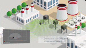
RADAR systems, ideal solutions for surveillance of large areas
Works in any weather situation
Radar sensors are extremely robust and insensitive. Weather, for example, does not affect them at all. Whether it’s snow, rain or fog, security personnel can rely on the detection working. The reflected signal is not affected by environmental influences.
Active day and night
Rarely found in a single technology: the sensors work regardless of lighting conditions. The receiver records every signal from objects within the detection field both in pitch darkness and in glaring sunlight. False alarms caused by poor visibility are excluded with this measurement procedure.
Extreme conditions
Radar technology not only works regardless of weather conditions and light, but is also extremely resistant: the operating temperature range of radar technology is quite wide. Double-digit negative temperatures or hot desert temperatures do not affect the sensors. In a difficult environment, for example with dust, dirt or humidity, they guarantee their precise capabilities.
Multitasking
Radar sensors do not focus on a single object but monitor all objects within a detection area. Furthermore, all information about an object is determined at the same time. This means that security personnel will immediately receive all the information relevant to safety, such as position, speed, distance and angle needed to assess the danger situation.
Anonymity
All objects detected via radar are automatically in incognito mode. Since there are no images, people cannot be identified. This makes it easier to comply with the strict regulations governing the surveillance sector. Applicable laws on personal rights also concern the surveillance of private property. By using radar sensors, companies secure their premises without collecting any personal data. Radar sensor technology even offers the possibility of spatial mapping like location technology. The technology represents objects on a map.
Smart technology
Radar sensors and systems are sophisticated and have a variety of functions. Intelligent signal processing allows objects to be tracked through data clustering. These distinguish between objects and assign them to specific categories such as person or vehicle. Irrelevant detected objects, such as a wild animal running by, are filtered out by the technology. The sensors can also learn during the “filtering” process: if the filter function classifies, for example, a fox, it excludes objects with similar properties in the future (if desired). Thanks to the information from the localization algorithm, radar systems trigger an alarm, for example, or control a connected camera.
Wide & Long Range
Electromagnetic waves have a very long range. Depending on the sensor, very remote objects can be detected. Some radar systems detect people and, of course, vehicles at a distance of up to 150 meters. Instead of a multitude of security applications with limited range, a single system covers the entire area to be protected. The wide coverage area gives security personnel valuable additional time: the sooner a dangerous situation is detected, the sooner action can be taken to protect against it.
Safe against vandalism
Security technology is often exposed to vandalism. In particular, cameras are common targets. Radar sensors generally have compact external dimensions. Positioned inside existing systems or behind a cover, they are hardly noticeable. Radar waves penetrate plastic and can therefore be well hidden and adapted, for example, to the design of a building, a technical system or a fence.
Maintenance? Simple!
The functional components are well camouflaged and protected from dirt by a plastic cover. If dust or dirt still manage to reach the sensors, this does not compromise functionality. Set it and forget it: even complex radar systems require no maintenance work. The sensor system reliably performs its job and therefore does not involve any effort on the part of the end user after installation, regardless of environmental influences.
Efficient
Radar reacts to the presence and movement of an object. As long as there are no new objects or people within the coverage range, security personnel can devote their work to other activities. However, as soon as a relevant event occurs, the security team is immediately alerted. Furthermore, radar also allows need-based control. This useful function makes a significant contribution to increasing efficiency. After all, connected devices such as a security camera can be aimed in a targeted manner, thanks to the sensor’s precise localization, and can be switched on or off according to actual needs. If everything is “quiet” within the coverage range, this saves energy by putting connected devices into standby mode without losing any detection.
Radar technology seems to have been created specifically for the security sector and is already paving the way for future applications, again in the field of security. Whether as an independent measuring instrument or as a supporting technology, the advantages are extremely important. The technology is interesting not only for typical security systems. The home automation sector is paying ever closer attention to home security issues. Here too, radar technology can provide support and innovative security solutions, such as smart alert or reminder functions. The combination of smart technology and the human mind should prove to be convenient and safe. So, there will be no way to get around smart sensors in the future.
What is a Brushless motor and how does it work?
Brushless motors are often mentioned, along with their various characteristics.
Given that many texts on the subject are quite complex, below we would like to share a video – developed by JAES – that, in our opinion, explains very well the characteristics, functions and advantages of a Brushless motor (such as service life, high efficiency, absence of sparking, etc.).
The advantages of the Brushless motor
Compact size, especially relative to the torque delivered
Absence of brushes, resulting in a longer product service life and less noise.
High efficiency and optimal performance conditions
Minimal noise
Disadvantages of the Brushless motor
Control is performed electronically by a controller/electronic device, so the cost of the control system – which must be reliable and easy to implement – must be added to the cost of the motor
To ensure proper management of Brushless motors, CONSYSTEM offers a wide range of BRUSHLESS MOTOR Drivers,
Ideal solutions to best control and set up the operation of Brushless motors.
These Brushless Motor drivers are designed to provide low audible noise, reliable and efficient performance, while reducing design cycle time thanks to simple parameter settings via a user-friendly GUI
An inverter is an electronic device whose function is to convert direct current (DC) into alternating current (AC) at a given voltage and frequency, using a DC power source.
Inverters are normally used to power storage batteries, systems, air conditioners, electric motors for vehicles, and UPS units – in short, wherever a conversion from direct current to alternating current is needed. The term “Inverter” can also refer to a “rectifier-inverter” assembly, powered by alternating current and used to vary the voltage and frequency of the output alternating current based on the input (for example, to power specific machine tools).
For a thorough, complete and simple explanation, below you can watch an excellent video developed by JAES
The various types of Inverter
There are three main types of inverter used to power AC loads:
square wave inverters (suitable for purely resistive loads),
modified sine wave inverters (suitable for resistive and capacitive loads; with inductive loads they can produce noise)
pure sine wave inverters (suitable for all types of loads because they faithfully reproduce a sine wave identical to that of our domestic mains supply).
What is the Hall effect? Advantages and solutions
Complex electronic controls have become part of everyday life. Household appliances are increasingly interconnected and intelligent, able to provide data and information in real time. Just think of the environment around us: refrigerators, ovens, washing machines, dishwashers, and in recent years all the smart home appliance solutions.
A scenario in which components play a leading role, and in which sensors play a key part in providing real-time data and information on the “status” of devices.
A special mention in this scenario goes to Hall sensors, widely used in modern household appliances.
But what exactly is a Hall sensor? And the Hall phenomenon?
What is the Hall effect? How does it work?
The Hall effect is an electromagnetic effect discovered in 1879 by the scientist E. Hall. It refers to the voltage measurable across a conductor (or semiconductor) when an electric current flowing through it is influenced by a magnetic field.
In summary: the Hall effect concerns the formation of a potential difference between the opposite faces of an electrical conductor; this difference is attributable to a magnetic field positioned perpendicular to the flow of electric current.
When a voltage V is applied to the terminals of a conductor, this (if it is DC) promotes a uniform flow of electrons from point A to point B, without any potential difference existing between two extreme points of a cross-section of the conductor (C – D) (Figure 1).
Figure 1: representation of electron flow in a circuit
If, instead, as shown in Figure 2, a magnet is brought close to the conductor, the flow of electrons undergoes a deviation from the straight path, caused by the influence of the magnetic field on the moving charges inside the conductor, creating a certain accumulation towards point D and a thinning in the area near point C.
Figure 2: representation of the change in electron flow caused by the proximity of the magnet
Under these conditions, in fact, a transverse voltage is generated perpendicular to the applied current, due to the balancing of the Lorentz force and the electric force.
The Hall effect and the Lorentz force. The blue arrows, B, represent a magnetic field passing perpendicularly through the conductive plate.
The fundamental physical principle behind the Hall effect is, in fact, the Lorentz force (as illustrated above). When an electron moves along a direction, v, perpendicular to the applied magnetic field, B, it experiences a force, F, the Lorentz force.
In response to this force, the electrons move along a curved path through the conductor, and a net charge, and therefore a voltage, develops across the plate. This Hall voltage, VH, obeys the following formula, which shows that VH is proportional to the intensity of the applied field and that the polarity of VH is determined by the direction, north or south, of the applied magnetic field. Thanks to this property, the Hall effect is used as a magnetic sensor.
Where:
VH is the Hall voltage across the conductive plate;
I is the current passing through the plate;
q is the magnitude of the charge of the charge carriers;
ρn is the number of charge carriers per unit volume;
t is the thickness of the plate;
The most noticeable electrical result is the presence of a voltage, between points C – D, indicated by the reading on the voltmeter.
The Hall effect sensor is built on this phenomenon; it is the component capable of detecting the generated magnetic field and the voltage difference, producing a signal (output) suitably converted into a standard according to the requirements of the electronic system.
In fact, by using the Hall effect in an IC, it is possible to measure the intensity of the magnetic field and create a wide range of Hall-effect integrated circuits for many different applications.
What is a Hall sensor made of?
There are two main variants of Hall sensors, divided according to output type: the analog version and the digital version. Let’s look at them in detail:
Hall sensor with analog output
Figure 3: block diagram of the Hall sensor with analog output
The basic component is normally equipped with three terminals and three “integrated” elements. As follows:
Code
Element
+ VCC
Positive supply voltage;
GND
Negative supply voltage;
USC
Output
STAB.
Voltage stabilizer circuit, whose role is to supply the entire circuit of the integrated sensor. The current is constant and independent of the supply voltage
SEH
Hall sensor
AMPL
Amplifier circuit dedicated exclusively to the Hall voltage; it is connected differentially so as to be sensitive only to the voltage difference present between the two faces of the Hall sensor. The output signal will then be ready for processing by analog or logic circuits.
Hall sensor with digital output
Figure 4: block diagram of the Hall sensor with digital output
This is the ideal solution for logic applications, where there are two states and the “all” or “nothing” information is normally needed.
Additional elements can be observed, in particular:
Code
Element
ELABOR ON/OFF
This is the processor, an element linked to the output of the operational amplifier. The processor triggers and changes its output level when the magnetic field exceeds a certain established threshold. The processor is equipped with hysteresis to avoid oscillations and uncertainties at the moment of triggering.
TR USC.
NPN switching transistor; the output is of the open-collector type so as to ensure adaptability with any type of circuit. The output allows the OR logic function, so that the signal from many sensors can be collected on a single input. This makes this type of Hall sensor widely usable.
This aspect brings further advantages for integration, since in some cases, thanks to proprietary switching algorithms integrated into the IC (integrated circuit) and GUI software, it is possible to transmit parameters via USB to the on-chip EEPROM, where they are used by the on-chip algorithm. This greatly simplifies development and integration.
What advantages does the use of Hall sensors bring in household appliances?
Given the current technological evolution, Hall sensors offer considerable
Wide range of use: thanks to digital and analog outputs, Hall-effect devices are versatile and widely used; they can be employed as proximity, positioning, speed and current detection sensors, all measurement phenomena linked to the Hall principle.
Long life: unlike a mechanical switch, this is a long-lasting solution since there are no mechanical wear issues.
Isolation and reliability. Hall-effect sensors are galvanically isolated. They can withstand much higher current values and voltage spikes without suffering any damage.
Ease of implementation and small size: a Hall-effect sensor can be inserted and implemented in complex projects with great ease, also given its minimal size and ease of connection with electronic circuits. This offers manufacturers significant economic benefits, since they can use a single standard component for all the different types.
Start typing to search…
Recent searches
Featured
No results for
This site is registered on wpml.org as a development site. Switch to a production site key to remove this banner.














































 Figure 4: Graphic representation of Flash LiDAR technology